Intraoperative skeletal traction in the dog
G. L. Rovesti, A. Margini Veterinary Clinic M. E. Miller, Cavriago, Reggio Emilia, Italy
F. Cappellari, B. Peirone School of Veterinary Medicine of Turin, Grugliasco, Turin, Italy
Introduction
The need for techniques for fracture reduction is often felt in veterinary orthopaedics and traumatology (1, 2). Nevertheless, the development of such techniques has not been very intense, particularly when compared with developments in human orthopaedics. Skeletal traction has been applied in a consistent way in humans for almost all types of fractures through the use of standardized reduction techniques, fracture tables and specific instruments that are designed for various patient positions. The use of skeletal traction in humans is standard procedure for both preoperative and intraoperative fracture reduction. The aim of our work was to evaluate the technical feasibility of a method of application of intraoperative skeletal traction to each of the appendicular skeletal segments for fracture reduction in dogs, similar to that employed in human orthopaedics.
Material and methods
appendicular skeletal segments (20 each for rs of dogs that had died for reasons unrelated to the investigation. The dogs weighed between 25 and 35 kg. A total of 80 appendicular skeletal segments (20 each for the humerus, radius and ulna, femur, and tibia) were evaluated. The procedures were performed using a surgical table (Ergomed 99, Med Matrix, Modena, Italy) which had special attachments and instruments to facilitate traction. For each skeletal segment, the dog’s body position on the surgical table, the opposition points, and the anchorage points for force application were identified.
The opposition points were defined as the points on the body where stabilization could be applied to counteract the traction forces and avoid translation, without injuring the patient. Anchorage points were defined as the points where traction could be applied distal to the fractured skeletal segment, without damaging the bone or the soft tissues.
The following instruments were used in this study:
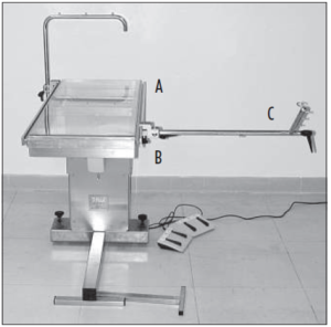
- A surgical table with lateral rails to which the clamps for holding instruments were connected, and a ·micrometric traction stand which could be lengthened by up to 20 cm (Fig. 1);
- Autoclavable nylon bands with a loop on one end that were placed on the distal anchorage points for the application of traction to the antebrachium and the tibia (Fig. 2);
- Nylon anchorage bands of various lengths that were applied to the opposition points to hold the patient on the table (Fig. 2);
- Aluminium hooks on the lateral rail of the table for anchorage of the nylon bands (Fig. 3);
- Stainless steel stabilizers were employed to hold the dog in certain positions on the table, and to also reduce pressure exerted by the nylon bands on the dog’s body (Fig. 3);
- An autoclavable, stainless steel traction stirrup was used for application of traction to both distal and proximal skeletal segments (Fig. 4);
- Limb rests connected to the lateral rails of the table were also used at certain opposition points (Fig. 5).
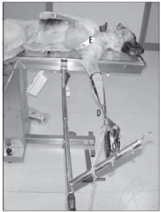
Fig. 2 Positioning for traction of the forelimb, with cranio-medial approach to the radius-ulna. The limb is subjected to traction by traction bands (D), and the dog’s body is held in position by nylon bands (E).
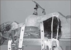
Fig. 3 Dorsal view of the same positioning as in Fig. 2. The tension of each band may be adjusted by attaching them to the aluminium hooks (F), which can run along the lateral rail of the table. Notice the use of a stabilizer (G) for the dog’s back. The nylon band over the neck that is used for patient stabilization, passes over the stabilizer, to avoid compression of the base of the neck.
Positioning for appendicular skeletal segment traction
Antebrachium
Cranio-medial approach: The dogs were positioned in lateral recumbency with the affected limb down and the contralateral forelimb maintained against the thoracic wall with the shoulder flexed. The neck was extended. The limb that was to be subject to traction was positioned with the midshaft of the humerus at the border of the table. The traction stand was attached to the table caudal to the forelimb, with the short component oriented cranially, so that traction could be exerted with the cranio-medial region of the antebrachium remaining completely unobstructed (Fig. 2).
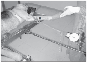
Fig. 4 Positioning for traction of the humerus. The traction is exerted via a traction stirrup (H) applied to the humeral condyle, so as to avoid damage to the distal structures, since the forces required for reduction of this segment are usually quite large.
Cranio-lateral approach: The forelimb subject to traction was placed uppermost with the dog positioned in lateral recumbency. The contralateral forelimb was flexed at the elbow and secured with the carpus under the dog’s muzzle. In all other respects, the
positioning of the dog and traction stand were the same as for the cranio-medial approach to the antebrachium.
Opposition points: Two bands were crossed over the sternum. A dorsal stabilizer was used on the dorsal area of the neck. The band crossing the upperside surface of the neck region was passed over the stabilizer (Fig. 3) so that excessive pressure on the base of the neck by this band could be avoided.
Anchorage points: For this traction technique, bands applied to the carpo-metacarpal region of the forelimb were usually used. The bands were coupled in order to evenly distribute the traction forces to both sides of the limb. Although not tested in this study, a transosseous K-wire could also be inserted through the distal epiphyseal region of the radius, or through the metacarpal bones for anchorage in case of older, displaced or over-riding fractures.
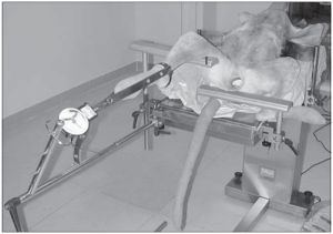
Fig. 5 Positioning for traction of the hindlimb for a bilateral approach to the tibia. The opposition point is provided by a limb rest (I).
Humerus
The dogs were positioned in lateral recumbency with the affected limb uppermost, similar to that used for the cranio-lateral approach to the antebrachium (Fig. 4). The traction stand was placed caudal to the forelimb with the short component oriented caudally, in order to exert axial traction on the humerus (Fig. 4).
Opposition points: A single band was passed circumferentially around the thorax in the region caudal to the axilla for surgical approaches of the entire humerus (Fig. 4).
For surgical exposure of the distal portion of the humerus alone, two bands crossing over the sternum were used. A dorsal stabilizer was used dorsal to the neck when two bands are used. The band crossing the upper surface of neck was placed over the dorsal stabilizer as for application to the radius and ulna.
Anchorage points: For this traction technique, the traction stirrup was used in conjunction with a transosseous K-wire through the condylar region of the humerus,
in a position that was compatible with the in a position that was compatible with the th esis technique (Fig. 4). The wire ends were connected to the stirrup arms by means
of bolts. Once secured, the wire was tensioned by the stirrup lever mechanism. This
tensioning avoided wire bending, and prevented soft tissues from being cut by the
bent wire. In preliminary testing we found that traction exerted with the bands applied to carpometacarpal region could damage the distal structures, before exerting any useful traction on the humerus, because t
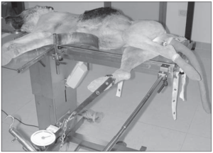
Fig. 6 Positioning for traction of the hindlimb for the cranio-medial approach to the tibia. The limb is subjected to traction by traction bands, and the dog’s body is held in position by nylon bands.
Tibia
Cranio-medial approach: The dogs were positioned in lateral recumbency with the affected limb down, and the contralateral hindlimb secured caudally with the stifle
flexed and the hip extended (Fig. 6). The limb that was being subjected to traction
was positioned with the midpoint of the femoral diaphysis overlying the border of the
table. The traction stand was positioned caudal to the limb, with the shorter component
of the stand oriented cranially, in order to keep the cranio-medial aspect of the tibia completely unobstructed (Fig. 6).
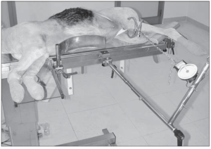
Fig. 7 Positioning for traction of the femur. The traction is exerted by a traction stirrup applied to the femoral condyle. The foot is kept elevated by a limb rest, to maintain axial alignment of the femur.
Combined medial and lateral approaches:
The dogs were positioned in dorsal recumbency. The limb being subject to traction was extended caudally, with a support placed in the popliteal region (Fig.5). The contralateral hindlimb was positioned in abduction with the joints flexed and secured such that the calcaneus was as close as possible to the ischiatic tuberosity. The traction stand was connected to the end of the table, slightly medial or slightly lateral to the limb, depending upon the proposed procedure (Fig. 5). Usually, two lateral stabilizers were applied in the thoracic region to maintain this position during traction.
Opposition points: For the cranio-medial approach to the tibia, two nylon bands were applied. One band was passed over the uppermost ilium, across the inguinal region and under the scrotum of male dogs, and then secured to the table caudo-dorsally. The second band was passed circumferentially around the caudal region of the abdomen and both ends were secured to the table dorsally.
For the combined medial and lateral approaches to the tibia, the oppositional forces were applied to the caudal part of the thigh by means of a limb rest placed in the popliteal region. Although not evaluated in the present study, padding could be applied to the limb rest and the traction force temporarily relaxed every 15–20 minutes if a longlasting traction was foreseen in a clinical setting.
Anchorage points: Coupled nylon bands were applied to the tarso-metatarsal region of the limb for traction in order to evenly distribute the forces along the longitudinal axis of the tibia. As for the humerus,the traction stirrup could potentially be anchored to a transosseous K-wire in the distal epiphysis of the tibia, or the metatarsal bones in cases of distal, over-riding fractures.
Femur
The dogs were positioned in lateral recumbency with the limb being subjected to traction uppermost. The contralateral limb was secured to the table caudally with the stifle flexed and the calcaneus positioned close to the ischial tuberosity. The traction stand was attached to the table cranial to the limb, with the shorter portion oriented caudally so that the traction could be exerted along the longitudinal axis of the femur. A limb rest was used to support the tarsus, in order to maintain the limb in a horizontal plane (Fig.7).
Opposition points: A band was passed across the abdomen caudally, just under the ilial wing, and then across the inguinal region, and under the scrotum of male dogs. The band was secured caudo-dorsally to the table. A second band was passed around the caudal region of the abdomen and both ends of this band were secured to the table dorsally.
Anchorage points: For this traction technique the traction stirrup anchored to a transcondylar K-wire placed in the distal end of the femur was used because of the strength of the thigh muscles and also because it was believed that traction exerted with bands encircling the tarso-metatarsus may damage the distal structures.
Application of skeletal traction
A dynamometer (Yo-Zuri America, Lucie, FL, USA) was secured to the short portion of the traction stand. Nylon bands secured to the metacarpal or metatarsal regions (Fig. 2), or a small chain connected to the traction stirrup (Fig. 4), was then connected to the dynamometer. Each skeletal segment was then subjected to traction by turning the handle of the traction stand, making it lengthen. The applied force was measured using a dynamometer, and was incrementally increased at a rate of 5 kg weight every two minutes, applying more traction as needed to maintain the scheduled force. Once a peak force of 25 kg weight was attained, traction was then maintained at this magnitude for half an hour. Each skeletal segment was then surgically exposed, and a mid-diaphyseal osteotomy was created using an oscillating saw. The radius and ulna were exposed and osteotomized via a medial approach to the radial diaphysis. If difficulties were encountered with making the ulnar osteotomy with the oscillating saw, then an osteotome was used to complete the cut. The humerus was exposed by a cranio-lateral approach, the femur by a lateral approach and the tibia by a medial approach. In some instances it was also necessary to use the osteotome to complete the fibular osteotomy. All displacement of the bone segments, due to the mismatch between the bone axis and the direction of the traction, was then corrected by manoeuvres with the traction stand until realignment of the skeletal segments was achieved. These manoeuvres were recorded.
Results
At the commencement of application of skeletal traction, it was found necessary to readjust the traction stand repeatedly so that the incremental increases in force could be maintained. However, as higher forces were applied, readjustment was seldom necessary. Once the peak force of 25 kg weight was achieved, the loss of load in the following half an hour was always very low, and never more than 3 kg weight. After the skeletal segment in traction was osteotomized, translation of the bone fragments by at least 100% of the bone diameter was observed in 5 radii, 12 humeri, 7 tibiae, and 14 femora. Each of these skeletal segments were successfully restored to normal alignment by manoeuvring of the traction stand.
Correction of varus or valgus malalignment was achieved by rotating the short portion of the traction stand in a clockwise or counter-clockwise direction, after temporarily loosening the attachment of clamp holding this bar. In this way, the tip of this bar was moved higher or lower than the starting point. For example, elevation of the tip of this bar resulted in correction of a valgus malalignment of the tibia that was being exposed using a medial approach. However, this technique was not found to be useful when the tibia was positioned for the bilateral approach. In this instance, correction of valgus or varus deformity was performed by loosening the clamp, and sliding the entire traction stand along the lateral rail of the table, either in a medial or lateral direction, respectively.
To correct for procurvatum or recurvatum malalignment, for all the positions except for the bilateral approach to the tibia, the clamp was loosened, and entire traction stand was pushed horizontally along the lateral rail of the table. The clamp and the connected traction stand were pushed toward the cranial part of the dog for the correction of procurvatus, and toward the caudal part for the correction of recurvatus. In the position for the bilateral approach to the tibia, the technique of upward or downward rotation of the shorter part of the traction stand was used for the correction of procurvatum and recurvatum malalignment, respectively.
To correct for procurvatum or recurvatum malalignment, for all the positions except for the bilateral approach to the tibia, the clamp was loosened, and entire traction stand was pushed horizontally along the lateral rail of the table. The clamp and the connected traction stand were pushed toward the cranial part of the dog for the correction of procurvatus, and toward the caudal part for the correction of recurvatus. In the position for the bilateral approach to the tibia, the technique of upward or downward rotation of the shorter part of the traction stand was used for the correction of procurvatum and recurvatum malalignment, respectively.
In 18 cases we experienced problems with slipping of the traction bands from the metacarpus or metatarsus during loading. This problem was overcome by repositioning the bands, or by placing them around the distal antebrachium or the distal end of the tibia, or by using a traction stirrup instead of bands.
Discussion
Performing skeletal traction was relatively straightforward for each skeletal segment. The loss of load in the first phase of the traction procedure was apparently due to the elasticity of the various elements of the system, including the soft tissues, the anchorage bands, and the traction bands which seem to absorb most of the force applied at low loads. For this reason, the traction stand was lengthened much more in the early phase than in the later stages to achieve the same increase in force applied to the skeletal segment. Once the elasticity of the system was overcome, the correlation between bar lengthening and force applied was almost directly linear. The small loss of tension during the half an hour after the peak force of 25 kg weight that was achieved showed that it is possible to maintain the applied force for long periods without significant variations from the steady state. This is usually not possible with the manual application of traction due to variations in the forces applied. The behaviour of the traction bands and stirrup were different. The bands were easy and quick to use, but they were prone to slide. The procedure was definitely hindered by sliding of the bands which would certainly be a problem in clinical practice if it occurred during fracture reduction. Greater lengthening of the traction stand was required to overcome the elastic phase of the traction bands, in comparison to the traction stirrup because the stirrup had minimal elastic behaviour. Excessive mechanical traction may also be potentially dangerous, and clinical evaluation of the technique is required.
The greater tendency for axial displacement of the bone fragments following the osteotomy of the humerus and femur, in comparison with the antebrachium and tibia, is likely due to the greater difficulty in matching the traction axis with these skeletal segment and surrounding musculature. However, we found that angular malalignment resulting from mid-diaphyseal osteotomies of the major appendicular skeletal segments of dogs could be consistently corrected to achieve an accurate reduction by the manoeuvres using a purpose built traction stand and table.